ZS6EY SDR Receiver: 7
February 2024
Introduction
A
large part of Amateur radio activities involves building new gadgets and this
gadget proved to be an interesting challenge. The idea for a home brew Software
Defined Radio (SDR) receiver design was mainly based on the need for a cost-effective
digital receiver that could be used to spot FT8 stations on HF without the need
to sacrifice an expensive radio. The receiver had to be tuneable across a wide
HF frequency range with accurate frequency simulation. Doing some internet
research provided plenty of ideas and options to purchase receiver components
or complete radios. The decision was made to rather attempt a new design with a
dedicated PCB with a small form factor. The design scope included: (i) affordable, (ii) local components and suppliers (iii) low
component count and (iv) digital signal processing.
The
SDR receiver design is based on the uSDX design by
Guido, PE1NNZ and Manual, DL2MAN and all credit to their amazing code wizardry
that makes the design possible. I have adapted the design to make the code and
functioning more understandable. This is an open source
project with the design and code freely shared.
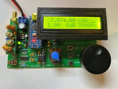
Figure 1 – Arduino Nano SDR Receiver
Circuit
Description
The
receiver is based on an 8-bit Arduino Nano running at 16 MHz and is in reality not really suitable for any digital signal
processing, but the design accomplishes a good audio response even effective
for FT8 decoding. With an Si5351 VFO breakout board providing the in phase and
quadrature local oscillator (LO) frequencies, the direct conversion frontend of
the receiver is the trusted quadrature detector designed by Nic Tayloe N7VE.
The receiver circuit diagram is adapted from the original uSDR
design as well as additional changes and simplifications based on various
designs found on the internet. Refer to Figure 4 for the circuit diagram.
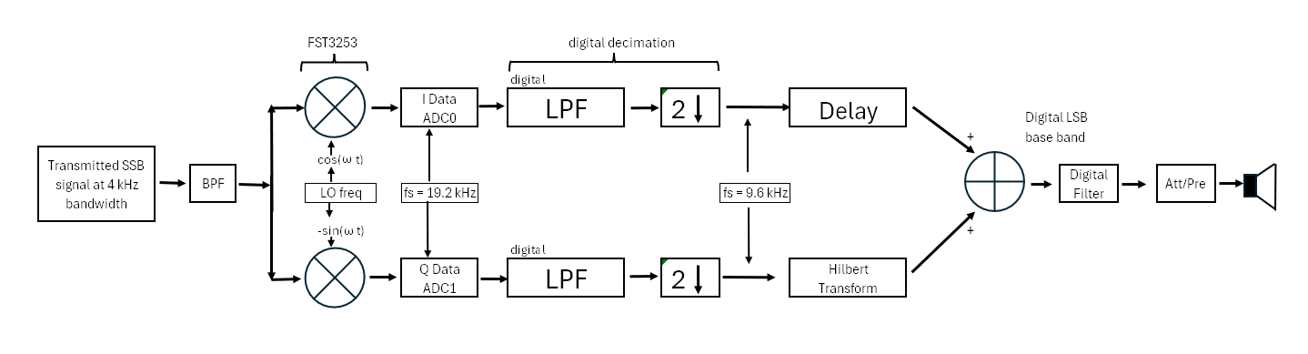
Figure 2 – Arduino Nano SDR Receiver
Block Flow Diagram
The
signal from the antenna is routed via a suitable band pass filter (BPF) and the
split into zero and 180 degrees out of phase signal by the trifilar
coil and fed into the FST3253 high speed multiplexer. The BPF is optional but it does improve the receiver performance at
higher frequencies. The modular BPFs from QRP labs are used. A voltage
divider is used as the DC bias at the trifilar coil
centre tap to provide the ADC zero point of 2.5 volts. The multiplexer divides
the incoming signal into 4 discrete 90-degree signals that are mixed in the LM4562
instrumentation dual operational amplifier (op-amp) to produce an in-phase base
band audio signal (I signal) as well as a 90 degree out of phase base band
audio signal (Q signal). The SI5351 VFO chip, controlled by the Arduino via the
I2C bus, is used to produce the in phase and 90 degrees out of phase LO frequencies
that are used feed the FST 3253 multiplexer. The frequency response of the op-amps
is set by the four capacitors grounding the 4 signals from the multiplexer as
well as the capacitors across the inverting input and output of the op-amps.
The gain of the op-amp is set by the resistor across the inverting input and
outputs. The In-phase signal is then fed
into ADC0 of the Arduino via a set of voltage dividers that is connected to the
Aref pin of the Arduino. More on this setup later. The quadrature signal is fed
to ADC1 of the Arduino also via a voltage divider. Further processing of the
audio signal is performed in the digital domain with no additional analogue
circuits used.
The
gain of the op-amp is set with the 82kohm resistors for a standalone design.
The IQ data from the op-amp can also be fed into a PC soundcard with suitable
software to decode the IQ data. HDSDR has been used with great success. For
this option resistors with 10kohm values are suggested to reduce the
amplification around the LO frequency as is required by the PC soundcard. The
receiver has a potential sampling bandwidth of 192 kHz if a suitable soundcard
is used.
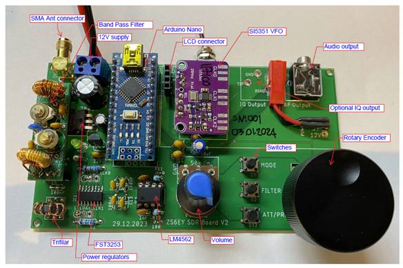
Figure 3 – Receiver components
Due
to the clock speed of the Arduino at 16 MHz the onboard ADCs (Analogue to
digital converters) are clocked as free running at around 19.2 kilo samples per
seconds alternating between ADC0 and ADC1. The full 10-bit ADC resolution is
used with the 2.5 volt ADC bias removed
mathematically. Once the signal is sampled it is down converted to 9.6 kHz to
reduce aliasing and provide a low pass filter on the sample to reduce noise and
remove unwanted high frequencies. To extract the required sideband information from
the data the quadrature signal is processed via a Hilbert transform to shift
the audio data by 90 degrees with the in-phase data delayed matching the
processing delay introduced by the Hilbert transform. The mixing of the two
signals is performed mathematically that rejects the upper sideband of the
audio data and then provides a lower side band audio sample. To produce an
upper sideband signal, the I and Q frequencies from the SI5351 is swapped
around before the signal is processed in the multiplexer.
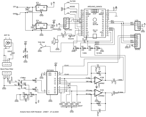
Figure 4 – Circuit diagram of the
Arduino Nano SDR receiver
The
Arduino does not have a dedicated Digital to analogue converter (DAC) and to
generate audio requires the use of the Pulse Width Modulation (PWM) function in
Mode14 on pin D9 running at a sample rate 62.5 kHz. The PWM sample rate is
higher than the ADC sample rate to ensure no degradation of the audio quality
takes place. The PWM is 8-bit only and the necessary down conversion is done on
the ADC signal. The audio quality is improved by loading the PWM with a new
audio value during every ADC sample instead of waiting for both ADC0 and ADC1.
This compromises the Arduino processing speed but significantly improves audio
quality. The audio output is sufficient to drive headphones or a speaker
through a suitable amplifier circuit.
The
Arduino and the LM4562 is powered directly from the 12V supply with a LM7805
linear power regulator feeding the other 5V users. A dedicated LM78Z05 is used
to power the FST3253 to provide power line isolation for the multiplexing
circuit.
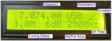
Figure 5 – LCD display details
Functions
There
are 4 switch selectable filters implemented in the
digital domain that spans 3600 Hz, 2900 Hz, 2400 Hz and 1800 Hz. There are two
preamps available with the +6 dB preamp implemented in software by multiplying
the mixed sample data by 2. The +13dB preamp uses the voltage divider at the
ADC inputs, as mentioned previously, to reduce the Aref pin voltage from 5 V to
the internal 1.1 V voltage refences to increases the ADC sampling sensitivity.
Two attenuators are provided in software for -6 dB and -9 dB by dividing the
mixed sample data by 2 and 4 respectively.
Due
to the quadrature limitation of the SI5351 chip the lowest frequency that can
be used is 3.5 MHz.
This limitation can be overcome but that would require additional
hardware and will place a limitation on the upper LO frequency.
A
simple S-meter is implemented to provide a basic indication of signal strength
and is updated every 200 ms. The rotary encoder
provided for manipulating the frequency is also interrupt driven to increase
the response with the rotary encoder push switch used to toggle the frequency
tuning steps of 1.0M, 100k, 1k and 0.5k. All the major parameters of the receiver
are saved to EEPROM that allows a fast reboot to previous operational
parameters. Finaly a I2C 16x2 LCD screen is provided as a display for the operational
parameters.
Conclusion
The
receiver has proven to be sensitive enough to allow for FT8 decoding as well as
a general use LSB/USB receiver with a usable frequency range of 3.5 MHz to 30
MHz. The implementation of the signal processing in the digital domain makes it
possible to change the functioning of the receiver by updating or changing only
the Arduino code to add more features. The receiver can be built for just over
R950 and has a good price to performance radio. Happy building!
Supporting
Documentation
Blank
PCB
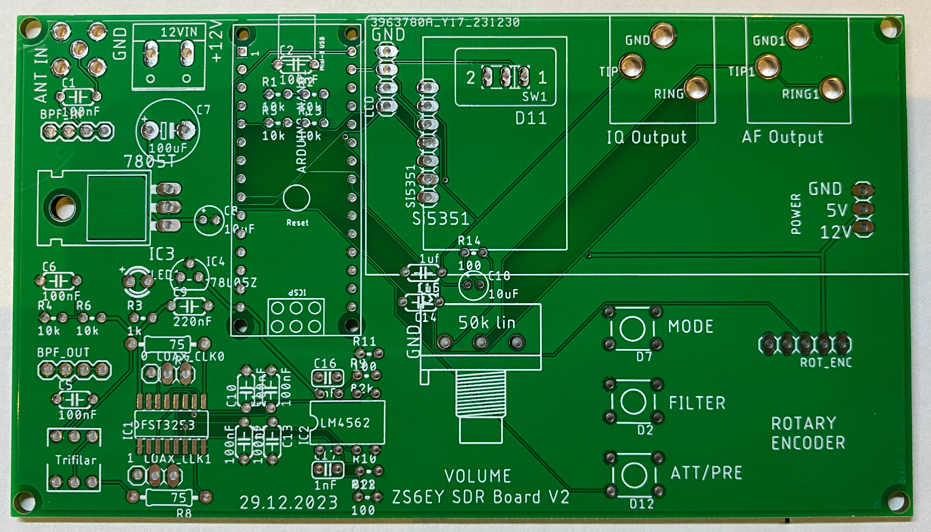
Figure 5 – Blank PCB
Arduino
Code
The
latest Arduino code is V1.22.16 and is available here.
PLEASE
NOTE: The SI5351 VFO chip will require initial calibration when the receiver is
first used. I have included the calibration sketch to obtain the calibration
factor to be used in the Arduino sketch in the same link as above. It is simple
to use and require a frequency meter that can accurately measure 10 MHz.
Building
the Receiver
Apart
from the FST3253 surface mount chip, all the components are through hole for
easy construction. The FST3253 chip is not difficult to solder with a bit of
patience and a small soldering iron. With reference to the parts list below;
not all of the components are readily available in
South Africa especially the FST3253 multiplexer that was ordered from Digikey in the US. The chip is only available as a surface
mount device. The LM4562 op amp is available from RS components at a reasonable
price. The trifilar coil that uses a FT37-43
toroid was only available from QRP Labs. One can use a larger toroid of the
same material but space is limited on the PCB. The
winding of the trifilar coil is explained by Hans on
page 11 of the building instruction for the receiver unit found here. Please send me an email if you
have any questions regarding the construction of the receiver.
3D Printed Parts
The radio uses two 3D printed
parts that provide a bezel for the LCD display as well as a standoff for the
LCD display that provides support for the screen just above the stereo audio
jack. The stl files are included in the link provided
above.
Gerber
Files:
The
Gerber files can be used to manufacture PCBs for the receiver. The files can be
found here.
Parts
List
|
SDR RX Board parts list - standalone |
ZS6EY |
29.12.2023 |
||
|
Part number |
Value |
Price (ZAR) |
Notes |
Part number |
|
Resistors |
||||
|
R3 |
1k 5% |
0.50 |
Local supply - Rabtron |
CR272 |
|
R1, R2,R4, R5, R6, R13 |
10k 1% M/F |
5.60 |
Local supply - Rabtron |
MF373 |
|
R9, R10 |
82k 1% M/F |
2.30 |
Local supply - Rabtron |
MF395 |
|
R7, R8 |
75 ohm 1% M/F |
2.30 |
Local supply - Rabtron |
MF323 |
|
R11, R12, R14 |
100 ohm 5% |
1.00 |
Local supply - Rabtron |
CR248 |
|
Capacitors |
||||
|
C1, C2, C5, C6,C10, C11, C12, C13 |
100 nF Monolithic |
10.00 |
Local supply - Rabtron |
MC100NF |
|
C7 |
100 uF 63 V electrolytic |
5.00 |
Local supply - Rabtron |
ER0100-063 |
|
C8, C18 |
10 uF 63V electrolytic |
10.00 |
Local supply - Rabtron |
ER0010-063 |
|
C9 |
220 nF monolithic |
1.00 |
Local supply - Rabtron |
MC220NF |
|
C14, C15 |
1uF monolithic |
4.14 |
Local supply - Rabtron |
MC1MF-2.5 |
|
C16, C17 |
470 pF ceramic |
1.60 |
Local supply - Rabtron |
CC470PF |
|
Semiconductors |
||||
|
IC1 |
FST3253 dual 1:4 multiplexer SOIC16 |
44.65 |
No local supply - Digikey only |
Digikey Stock No SN74CBT3253DR |
|
IC2 |
LM4562 dual low noise op-amp 8DIP |
57.80 |
No local supply - Digikey or RS only |
RS stock no. 197-7299 |
|
IC3 |
7805T 1A voltage regulator |
10.35 |
Local supply - Rabtron |
7805CT |
|
IC4 |
78L05 100 mA voltage regulator |
5.00 |
Local supply - Rabtron |
78L05 |
|
LED1 |
3mm Green LED |
1.82 |
Local supply - Rabtron |
L3G |
|
Miscellaneous |
||||
|
Trifilar coil |
FT37.43 toroid |
15.00 |
No local supply - QRP labs only |
|
|
Wire |
1m 0.3mm enamelled copper wire |
5.00 |
Local supply - Rabtron |
|
|
BPF module |
Optional |
104.00 |
Radio winkel or QRP Labs |
|
|
Socket |
2X 4 Way header sockets |
2.76 |
Local supply - Rabtron |
YTS1NS04 |
|
Socket |
2x 15 way socket |
12.56 |
Local supply - Rabtron |
YTS1N15 |
|
Socket |
1x 4 way socket |
3.45 |
Local supply - Rabtron |
YTS1N04 |
|
Socket |
1x 8 way socket |
2.30 |
Local supply - Rabtron |
YTS1NS08 |
|
Pin header |
1 x 40way header |
6.05 |
Local supply - Rabtron |
S/HEADER40W |
|
SMA 90 deg connector |
12.30 |
Local supply - make.net.za |
Right Angle Female SMA PCB Connector |
|
|
Arduino Nano CH340 |
218.00 |
Local supply - Rabtron |
ARDNANO3 |
|
|
Si5351 board
25 MHz |
101.00 |
Local supply - robotics.org.za |
SI5351-MOD |
|
|
Audio 3.5 mm socket |
x2 |
36.00 |
Local supply - Rabtron |
3.5SOCKETSTPCB |
|
2 way terminal block con |
2.60 |
Local supply - Rabtron |
CMM5-2 |
|
|
DIP 8 IC socket |
2.30 |
Local supply - Rabtron |
USO08 |
|
|
Rotary encoder |
39.00 |
Local supply - Rabtron |
ARDENCODER |
|
|
16x2 LCD display with I2C board |
79.00 |
Local supply - Rabtron |
LCD16X2BLBLUE |
|
|
PCB |
115.00 |
|||
|
Miniature toggle switch |
x1 |
20.00 |
Local supply - Rabtron |
SMTSSPDT |
|
Tactile switches |
x3 |
6.00 |
Local supply - Rabtron |
B1721A |
|
50 k potentiometer |
x1 |
12.00 |
Local supply - Rabtron |
CPP50K |
|
Aluminium Knob |
x1 |
28.00 |
Local supply - robotics.org.za |
ALU-1332 |
|
Estimated Total |
ZAR 979.63 |
|||