ZS6EY GPSDO Project:
Radio Amateurs will always have the need for an accurate frequency standard that will provide a reasonable accuracy to cost ratio. This piece of kit is known as a GPS Disciplined Oscillator (GPS DO). There are numerous designs that one can find across the Internet but in true HAM spirit the decision was made to pursue a new design based on components that are readily available.
The design mandate:
- As cheap as possible with 1 Hz accuracy across the frequency range
- Use through hole components as far as possible
- Powered directly from the USB port
- Provision for an I2C LCD module
- 2 independent frequency outputs
- 2 frequency programs switchable without reprogramming
Design Details:
The unit was designed using off the shelf components in order to limit the amount of SMD soldering required. The following components are used:
- Arduino Nano
- U-blox 6M GPS module
- SI5351 VFO breakout board (2 x SMA female PCB connectors)
The three boards are located on a custom PCB with a few through hole components. The following components are required:
- 1x 330 Ω 5% resistor
- 1x 4.7 kΩ 5% resistor
- 1x 100 Ω 5% resistor
- 1x 3mm red LED
- 1x SPDT miniature toggle switch
- 1x UFL to SMA female pigtail
- 1x 4.7 uH 620 mA inductor
- 1x 18B20 temperature sensor
- 2x 220 nF monolithic capacitors
- 2x 10 nF monolithic capacitors
- 1x 10 uH 160 mA inductor (TCXO modification)
- 1x 1 nF SMD capacitor (TCXO modification)
- 2x 47 Ω SMD resistors
- 12.8 MHz TCXO (RS-online stock item 144-2371)
The stock SI5351 VFO breakout board is populated with a 25 MHz crystal that tends to drift too much for an accurate and stable frequency output. The Arduino sketch download area provides a sketch where the 25 MHz crystal can be used.
It was decided to replace the 25 MHz crystal with a 12.8 MHz TCXO that provides very good frequency stability and accuracy.
The PCB is designed to fit in the standard RS online aluminium extruded case part number 773-3047
Frequency update:
The GPSDO has been configured with 2 programs:
- Program 1 (toggle switch up) CLK 0 = 10 000 000 Hz and CLK2 = - Hz
- Program 2 (toggle switch down) CLK 0 = 10 000 000 Hz and CLK2 = 40 000 000 Hz
In order to change the pre-programmed frequencies or frequency allocation the Arduino sketch has to be changed. Unless you want to change the pre-programmed frequencies there is no need to update the firmware. The update of the Arduino sketch is not complex at all.
The GPSDO is programmed with Arduino IDE and can be found here https://www.arduino.cc/en/software
Before you can open the sketch you first need to download and install the IDE software.
The sketch is available from the following OneDrive link. Please ensure that you download the sketch that reflects your GPSDO serial number since the calibration factors for each unit is different. The latest firmware is version V2.02ah 12.8.If you have a need for different frequencies, you can follow the following procedure:
The snipped of code below is where the changes are made:
//**************************************************************************
// ************************ MAKE FREQ CHANGES HERE ************************
// *************************************************************************
//Read the frequency setting pin
res = digitalRead(4);
// When testing with the frequency beat method, add or substract 800 Hz (or your choice).
if (res == HIGH)
{
// ********** PROGRAM 1 **********************
Freq_1 = 10000000; // toggle switch to 5V
Freq_2 = 0; //
lcd.setCursor(5, 0);
lcd.print("P1");
Serial.print(" -Program 1- Clk0=");
Serial.print(Freq_1);
Serial.print(" Hz Clk1=");
Serial.print(Freq_2);
Serial.print(" Hz 6mA Cal=");
Serial.println(XtalAvg);
digitalWrite(6, HIGH);
delay (200);
digitalWrite(6, LOW);
}
else
{
// ********** PROGRAM 2 **********************
Freq_1 = 10000000; // toggle switch to ground
Freq_2 = 40000000; //
lcd.setCursor(5, 0);
lcd.print("P2");
Serial.print(" -Program 2- Clk0=");
Serial.print(Freq_1);
Serial.print(" Hz Clk1=");
Serial.print(Freq_2);
Serial.print(" Hz 6mA Cal=");
Serial.println(XtalAvg);
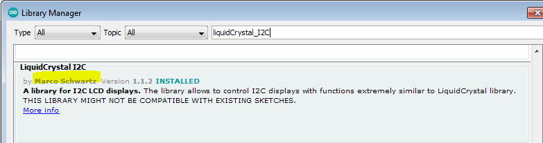
Once you have changed the frequencies, you need to compile the sketch . In order to do that you need to load the following library: go to Tool, Manage Libraries and in the search area type LiquidCrystal_I2C and load the library by Marco Schwartz. Install version 1.1.2
The GPSDO uses the Arduino Nano with the Arduino Pro or Pro Mini board and ATmega328P 5V,16MHz processor or the default Arduino Nano board. Select as in the screen shot below:
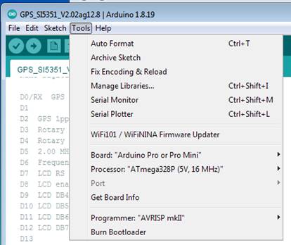
The programming port of the GPSDO becomes an option once connected to your PC. Select the correct port form the list.
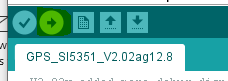
Click the upload bottom (right arrow) to upload an updated sketch.
The serial monitor can also be used to monitor the GPSDO serial output.
Operation:
The GPSDO is simple to operate and use.
- Select the program you want to use by setting the miniature toggle switch up for P1 and down for P2.
- Connect an active GPS antenna to the SMA connector next to the LED.
- Connect clock output 0 and/or 1 to the device you want to discipline.
- Connect the USB cable to the mini USB port on the Nano and a USB port or power device.
The red LED will flash once or twice to indicate the program selected and then settle into a once per second flash pattern until stationary that indicates the GPSDO is locked. The SMD LED on the GPS board will also flash once per second to indicate GPS Satellite lock.
The unit takes about 4 minutes to lock to the GPS 1 PPS signal.
The GPSDO outputs a detail diagnostic data stream at 9600 Baud rate to indicate various parameters that can be used for troubleshooting as well as displaying the active calibration parameters. The Arduino IDE serial monitor or any suitable terminal program can be used to view this data.
Technical details
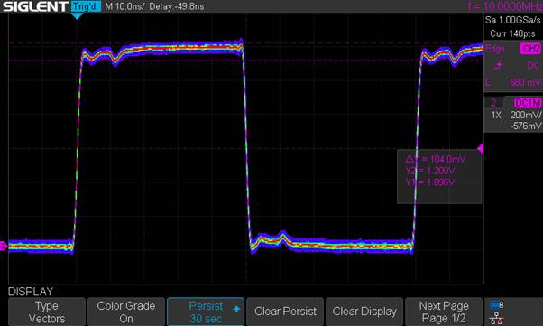
The output from the GPSDO unit is a square wave as can be seen in the picture below for the 10 MHz output.

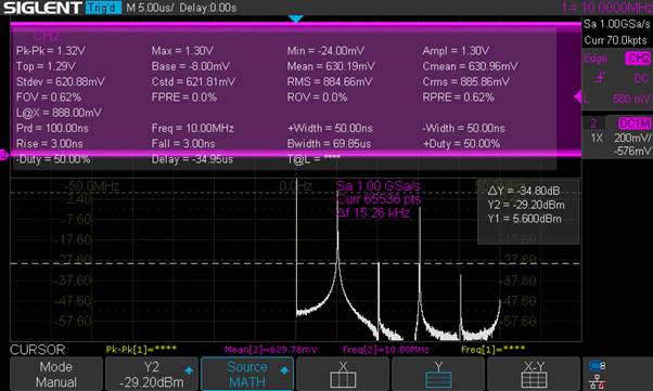
With a Fast Fourier transform function analysis the second harmonic is at 20 MHz and 38.2 dB below the main signal threshold.
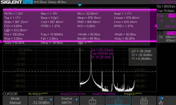
A 30 second colour persist display from the scope shows the low jitter on the signal
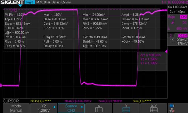
For comparison the Leo Bodnar unit is also tested at 10 MHz and the signal trace and Fast Fourier Transform showing the second harmonic is only 34.8 dB below the main frequency.
All screen captures from a Siglent SDS 1202X-E 200 MHz digital storage scope.
The current firmware can only accommodate frequencies op to 80 Mhz.
Applications:
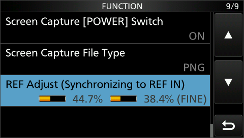
The GPS DO has been tested with the Icom IC-9700 to supply the 10 MHz reference signal as was implemented in the Icom firmware 1.26 update. Simply connect the clock output set to 10 Mhz to the SMA at the back of the Icom and select REF Adjust under the Menu, Set, Function menu option.
The GPSDO was also tested as frequency reference for the ADALM Pluto at 40 Mhz.
Building the unit from scratch
The GPSDO is supplied and calibrated as a complete unit. The following information is shared in case there is a need to build the unit from scratch.
The Onedrive link provides the following additional downloads:
- GPS Antenna bracket 3D printer STL file
- The TCXO enclosure 3D printer STL file
- The GPSDO PCB Gerber files that can be uploaded to JLCPCB for manufacturing.
The construction of the GPDSO unit comprises of populating the components and soldering.
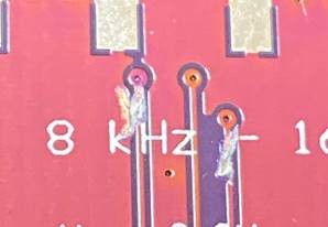
The SI5351 VFO board must be modified as shown in the next picture by cutting CLK 0 and CLK 2 pcb track to isolate it from the pin header. If this is not done, the frequency stability of the SI5351 VFO is affected.
The SI 5351 board can be used with the 25 MHz crystal but as mentioned earlier it does not provide the accuracy required for the GPSDO.
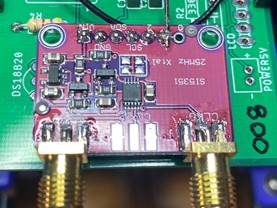
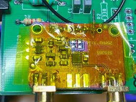
The 25 MHz crystal must be de-soldered with a hot air station as shown. Use kapton tape to reduce the heat stress on the neighbouring components.
The 12.8 MHz TCXO is wired as shown with the inductor used to feed the 3.3V to the TCXO. The GND and Output as indicated
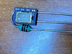
The 1 nF SMD capacitor must be installed as close as possible to the TCXO 3.3V and GND pins as suggested by the datasheet.
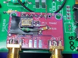
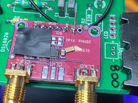
The 18B20 temperature sensor is installed as shown with the 3D printer temperature housing placed. A pin is added to the CLK 1 output of the SI5351 for calibration and measurement of the TCXO frequency.


The SMA connectors and the 47 Ω SMD resistor are placed to ensure a 50 ohm impedance at the frequency outputs.
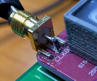
Complete GPSDO with hot glue in the TCXO holder. A jumper is added between the GPS 1PPS pin and the PCB pad.

Calibration
The unit is calibrated with the PPL Factor and Xtal Average value.