An ESP32-based rotator controller with a built-in web interface, 20×4 LCD, rotary encoder and physical buttons. It reads the rotator’s position feedback on an ADC input, converts it to azimuth from stored calibration points, and drives separate CW and CCW relays.
Includes automatic and manual calibration, park and three presets, WSJT-X grid-bearing integration, USB serial control, an optional temperature sensor with history graph, and OTA firmware updates.
Safety: the controller operates an antenna rotator with energised direction relays. Confirm the antenna and rotator can move freely, that wiring and limit arrangements are correct, and that the installation can be stopped safely. Do first tests with the drive supply isolated where possible. Never assume a software limit substitutes for mechanical protection.
Source basis: values and behaviour on this page were reviewed against the v97.14 source (Rotator_Controller_ESP_v97.14.02.11.2026.ino, guide dated 2 November 2026). Hardware supply voltages and exact PCB wiring depend on your installation, so verify against your assembled PCB. Firmware compile and on-hardware behaviour have not been independently validated for this guide.
1System overview
The ESP32 reads the rotator rheostat voltage on ADC1 GPIO34, converts it to antenna azimuth using stored calibration points, and drives separate CW and CCW relays.
The controller supports a 20×4 I²C LCD, a rotary encoder, physical direction and park buttons, a browser interface and USB serial protocols. Optional features include WSJT-X UDP grid-bearing integration, DS18B20 temperature monitoring and a 120-minute temperature graph.
Figure 1: conceptual rotator measurement and control architecture.
Pin assignments
Function
ESP32 pin / interface
Notes
Position feedback
GPIO34 (ADC1)
Analogue input; external divider/filter and common reference as designed
CW relay
GPIO16
Default active LOW
CCW relay
GPIO17
Default active LOW
Brake relay
GPIO18
Default active LOW
Spare relay
GPIO19
Optional
Cooling fan
GPIO13
N-channel MOSFET, active HIGH
Encoder CLK / DT / switch
GPIO32 / 33 / 25
Switch uses input pull-up
CW / CCW / Park buttons
GPIO26 / 27 / 14
Active LOW to ground
LCD I²C SDA / SCL
GPIO21 / 22
Firmware probes 0x27; 20×4 LCD
DS18B20
GPIO4
Optional temperature sensor
USB serial
9600 baud
Default protocol: EYRotator
1AFirmware installation: full BIN
Before applying motor power, connect the ESP32 to a Windows PC using a USB data cable and identify the serial COM port in Device Manager. In the EY Rotator ESP32 Flash Utility, select the ESP32 chip, choose the matching v97.14 full firmware image and flash it at address 0x0000. Wait for completion, then restart the controller.
The merged full BIN contains the bootloader (0x1000), partition table (0x8000), boot_app0 (0xE000) and application (0x10000). Use the correct 4 MB flash configuration and matching partition scheme.
Full BIN vs OTA BIN: a standalone application BIN is not interchangeable with a merged full BIN. ElegantOTA requires the application-only BIN, not the full image. The firmware .ino file alone is not a flashable BIN.
For a firmware upgrade, the retained NVS configuration normally preserves Wi-Fi, calibration and other saved settings. For true factory defaults, a full factory reset or erased configuration NVS is required. This also removes saved calibration and Wi-Fi credentials.
Example esptool command
Adjust the COM port, esptool location and file path. The filename is illustrative; use your actual full BIN.
Before applying motor power, verify relay polarity, correct GPIO wiring, ADC input voltage and common/isolated references according to the PCB design. The firmware assumes active-LOW relays on a fresh installation.
Power the ESP32. If valid Wi-Fi settings are absent or the connection fails, the controller starts its local configuration access point.
Connect a phone or computer to the open Wi-Fi network Rotator-Setup, then open http://192.168.4.1 in a browser.
Enter your local 2.4 GHz Wi-Fi SSID and password on the Wi-Fi configuration page. Saving credentials restarts the controller. If the details are wrong, the AP is available again after the connection attempt fails.
Once on the LAN, open the ESP32 IP shown on the LCD, or use the configured hostname or network discovery where available. Open Setup to inspect calibration and other settings.
The Home Wi-Fi setup page.
Important: the fallback AP is open (no password). Setup authentication exists in v97.14 but is OFF by default, so enable it and use unique credentials. Do not assume Setup authentication also protects every motor-control endpoint.
3First-use calibration: two paths
A fresh installation or full factory reset requires valid CCW/CW endpoint calibration before ordinary automatic movement is enabled. Wi-Fi configuration is not a prerequisite for commissioning if the AP-mode LCD calibration screen is available.
Figure 2: first-use calibration and normal-operation flow.
3A. Standalone LCD auto-calibration (no Wi-Fi connection)
Figure 3: LCD calibration screens. ADC values are illustrative.
With the configuration AP active and calibration required, the LCD displays CALIBRATION REQUIRED, WiFi AP: ACTIVE, Press ENC to AutoCal and the AP IP.
Ensure the rotor can safely traverse to both mechanical endpoints. Press and release the encoder switch once to start.
The LCD shows AUTO CALIBRATION, the active CCW/CW leg and the live ADC reading. A deliberate encoder press while running aborts calibration.
The firmware drives to the CCW limit, observes stable feedback, then drives toward the CW limit. Allow the entire sequence to complete.
After success the LCD displays CALIBRATION COMPLETE, both captured ADC values and Press ENC to SAVE. Press and release the encoder switch again to save.
The endpoints are committed to NVS, the calibration interlock clears, and the rotator can be operated locally without a working Wi-Fi connection.
The firmware allows 120 seconds per automatic calibration leg. Endpoint detection uses a stable ADC window of approximately 4 seconds, plus a CW-leg travel/span plausibility check. A failed or aborted sequence does not authorise normal operation. The Save press is separate from the Start press.
3B. Web-based auto-calibration
Connect to the ESP32 web Setup page (LAN or configuration AP).
Select AUTO CALIBRATE and monitor CCW/CW progress and ADC status.
After success, the green SAVE CALIBRATION button appears beside ABORT CALIBRATION.
Press SAVE CALIBRATION to commit the endpoints to NVS. Successful detection alone does not save them.
The calibration section of the Setup page.
3C. Manual three-point calibration
Use manual capture if the physical −180°, North 000° and +180° reference positions can be positioned accurately. Capture the CCW and CW endpoints from Setup while the rotator is stationary. Then position at true North and capture the optional North point. The North measurement corrects midpoint asymmetry.
The endpoint captures must be plausible. Changing either endpoint invalidates the previous measured North point.
If North has not been measured, the firmware uses (ADC_CCW + ADC_CW) / 2. The Setup button indicates whether North is calibrated and, when measured, shows the signed Delta ADC = ADC_North − calculated midpoint. The stored keys include adcccw, adccw, adcnorth and northvalid. The calibration-required interlock is tracked separately.
4Position measurement and ADC principles
The 500 Ω rotator rheostat produces a position-dependent voltage. The PCB analogue divider and filter scale it for the ESP32 ADC. The original hardware concept spans about −180° at the CCW endpoint, through North (000°), to +180° at the CW endpoint. Actual ADC counts depend on the divider ratio, reference voltage, wiring and ADC response. Never assume the example count of 2994 applies to every PCB.
The ESP32 ADC is 12-bit nominal. The firmware samples GPIO34 repeatedly, applies trimming and filtering, and can distribute samples across complete nominal mains cycles (50 Hz default) to reduce AC interference. It uses different filtering while stationary and while moving, balancing a stable display against timely motor stopping. Test changes to sampling, filtering and overshoot settings carefully.
4A. Two-segment calibration mapping
Figure 4: ADC endpoints and optional measured North calibration.
Let C be the measured CCW ADC, N the North ADC (measured or calculated) and W the CW ADC. For a reading A between C and N, azimuth is interpolated across −180° to 0°. For A between N and W, it is interpolated across 0° to +180°. Negative azimuths are wrapped for the 000–359° compass display. This allows different slopes on the two sides of North.
θ = −180 + 180 × (A − C) / (N − C) for C ≤ A ≤ N θ = 180 × (A − N) / (W − N) for N ≤ A ≤ W
These explain the three-point method; the actual source also handles wrapping, filtering and limits.
Example: C = 0 and W = 2994 give a calculated N of 1497. If the measured N is 1542, Delta ADC = +45. The midpoint offset is a useful comparison between resistor-divider PCB variants, but it is not itself an angle error without conversion through the calibrated slopes.
4B. Turn and safety functions
A web, USB or physical-button command requests an azimuth or direction. The LCD command-origin indicator distinguishes WEB, USB and BTN.
Automatic target movement uses ADC position feedback, a configurable deadband, overshoot compensation and short-turn settings.
CW and CCW relay commands are interlocked in software. Braking and relay-off delays are controlled separately.
A 120-second default motion timeout and a feedback-stall safety check protect normal travel. The calibration sequence has its own 120-second-per-leg timeout.
The controller rejects unreachable headings with TARGET OUT OF RANGE and blocks ordinary movement when calibration is required.
During an automatic turn, the first physical direction-button press stops the turn. Release before starting manual movement.
4CFirst controlled motor turn
Confirm that CCW and CW calibration has completed and has been saved. Check that the displayed azimuth is stable and matches the physical direction.
Verify that the mechanical end stops and the motor isolation / STOP arrangements work. Keep the antenna and rotator clear of obstacles.
On the Mobile dashboard, enter a target only 5–10° from the present azimuth, well away from the CW and CCW limits.
Press TURN TO (target). Changing the target field alone does not command motion. Observe the actual direction and azimuth feedback.
Confirm the controller stops close to the target. Use STOP or isolate motor power immediately if movement is incorrect.
Repeat a small movement in the opposite direction. Only then test longer moves, PARK, presets and the 180° turn function.
Caution: do not use CW LIMIT, CCW LIMIT, PARK or 180° TURN for the first live motor movement.
5Web interface
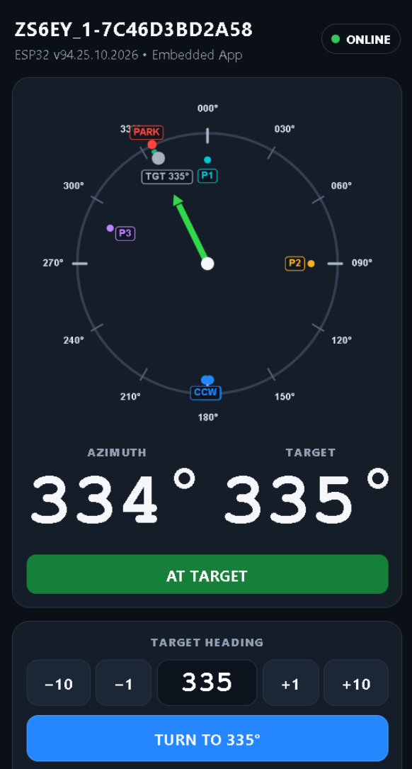
The Mobile dashboard, annotated.
The Mobile dashboard and what each control does.
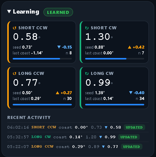
The Diagnostics panel expands when selected.The rotational learning panel.
The rotational learning algorithm can be activated in Setup, allowing the controller to estimate turn overshoot more accurately.
v94.01 compass update: the Mobile compass draws a translucent red pie-shaped keep-out sector from the centre to the circumference between the configured CW and CCW limits. With the defaults (CW 179°, CCW 181°) this is a narrow 2° wedge around south. The screenshot above predates this overlay; the on-device display is authoritative.
The red wedge is a display aid only. Software and physical motion protections remain separate. CW/CCW markers, preset markers and target indicators continue to be displayed.
6Operating controls
Control
Typical use
Web dashboard / Classic view
View azimuth and target; command turns, park, presets and grid-based bearings
USB serial
EYRotator or Yaesu-compatible remote control at 9600 baud (select the protocol in Setup)
CW / CCW pushbuttons
Manual directional operation; the first press during an auto-turn stops it
Park button
Request the stored Park position
Rotary encoder + LCD
Local operation and Setup; during AP commissioning, press to start, abort or save auto-calibration
WSJT-X UDP
Optional, disabled by default; reads grid information, then requires user action for the bearing turn
WSJT-X grid bearing integration
To use the WSJT-X interface, first activate the UDP listener in Setup (default is OFF) and enter your own grid location in 6-character format.
In the rotator Setup page, turn Grid Bearing / Distance and WSJT-X UDP Listener ON, enter your 6-character local grid locator and keep the UDP port (default 2237).
In WSJT-X, open Settings → Reporting and add the IP address of the router in the UDP text box. Save.
When you double-click a DX station, its grid locator is transferred automatically to the grid square box on the dashboard. Select Calculate to get the short-path and long-path directions.
Setup options for grid bearing and the WSJT-X UDP listener.
Short-path and long-path results after selecting Calculate.
7Temperature history and storage
The optional DS18B20 sensor on GPIO4 is read using non-blocking conversions. The Setup page graph covers 120 minutes, with a sample every 30 seconds. Current, minimum and maximum temperatures are shown, and unavailable readings appear as gaps.
The firmware uses a RAM circular buffer (241 positions) and LittleFS snapshots nominally every 5 minutes. It can initialise an unmountable filesystem by formatting the filesystem partition. This may erase other filesystem files but does not intentionally erase the separate NVS partition. History restoration depends on a synchronised clock. The Setup diagnostics report filesystem readiness, time synchronisation, saved sample count and save/restore state. SAVE HISTORY NOW allows an immediate test.
Test persistence: verify LittleFS READY and clock SYNCED, accumulate several samples, press SAVE HISTORY NOW, restart without erasing flash, and verify that earlier timestamped points return. Power-off periods should remain gaps. Use the selected 4 MB flash partition scheme with a usable filesystem region (for example 1.2 MB APP / 1.5 MB SPIFFS).
8Setup options and factory defaults
These are the values used when the corresponding NVS keys do not already exist. Existing stored settings override them. Some values are placeholders or dynamically managed, and are not proof of completed calibration.
Show the full defaults table
Category / setting
Default
Wi-Fi AP / IP
Rotator-Setup (open) / 192.168.4.1
Wi-Fi mode
DHCP; SSID and password initially blank
NTP / UTC offset / DST
pool.ntp.org / +120 minutes / OFF
Calibration CCW / CW ADC
0 / 2994 (placeholders; the calibration interlock applies)
North calibration
Calculated midpoint 1497; measured North OFF
CW / CCW travel limits
179° / 181° (internal wrapped convention)
Park position
000°
Long Cal CW / CCW (overshoot)
1.5° / 1.5° (replaced by the learned value in LEARNING/FROZEN)
Short-turn threshold / Short Cal CW / CCW
5.0° / 1.5° / 1.5°
Target deadband
±1.0°
ADC samples
576
ADC processing / stationary smoothing
ON / ON
Auto-learn overshoot
OFF (Setup: OFF / LEARNING / FROZEN)
Mains synchronisation
ON; 20,000 µs period (50 Hz); 250 max samples/cycle
Moving ADC response / update interval
95% / 40 ms while turning (100 ms stationary)
Cooling fan (GPIO13)
AUTO; fan ON ≥ 40 °C, OFF ≤ 35 °C
Relay active level
LOW
Normal motion timeout / brake delay
120 s / 500 ms
Button debounce
150 ms
Web refresh
500 ms
LCD heartbeat / leading zero / park marker
ON / ON / ON
LCD digit style
Compact 2×3 (v94 default)
LCD Setup menu / show target T
OFF / OFF
DS18B20 temperature display
ON
Compact dashboard / mobile compass
Compact dashboard OFF / mobile compass ON
Speech mode / announcement interval
OFF / 10°
USB serial protocol / diagnostics
EYRotator / OFF; serial 9600 baud
WSJT-X UDP / port
OFF / 2237
Grid-bearing support / local locator
ON / blank
Auto-calibration timeout
120 seconds per leg (fixed constant)
Temperature history
120 min / 30 s sampling / 5 min flash save
Mobile large azimuth/target / compass labels
ON / ON
Mobile compass prohibited sector
Translucent red pie wedge between the CW and CCW limits (v94.01)
Setup authentication
OFF initially; configure a username and password before network use
MQTT
OFF by default; broker host, port, username and password blank until set in Setup. Topic prefix: EYRotator/<device id>/, where the device id is the rotator name plus the full 12-hex-digit ESP32 MAC address
9Troubleshooting and verification
Symptom
Check / action
No LAN connection
Check SSID/password, the 2.4 GHz network and DHCP. Connect to the Rotator-Setup AP at 192.168.4.1
CALIBRATION REQUIRED
Complete and explicitly save endpoint calibration via the LCD (AP mode) or web Setup
Calibration failed / timed out
Check physical travel, rheostat wiring, ADC progress, relays and mechanical stops; inspect the LCD/web status
North not calibrated
Expected after endpoint auto-calibration; the midpoint is used until a manual North capture
Wrong azimuth or non-linear response
Check the ADC divider, a stable reference, endpoint capture and the optional North correction
Motor fails to start
Check the interlock, fault status, relay polarity, supply voltage under load and the timeout
Temperature graph empty after reboot
Check LittleFS READY, NTP SYNCED and the saved sample count; use SAVE HISTORY NOW and retest
Unexpected LCD source label
WEB = browser, USB = serial, BTN = local; verify the command source and firmware build
10Commissioning acceptance checklist
Relay outputs inactive at power-up
5 V / 3.3 V rails stable under relay load
ADC feedback monotonic across the mechanical range
CCW and CW calibration completed and saved
North captured, or calculated midpoint acknowledged
Physical STOP and direction buttons verified
Web and USB source labels verified where applicable
Travel limit, stall and timeout protections checked
Temperature reading and history storage verified
Configuration exported / backed up after commissioning
Scope and pending improvements: earlier firmware audits identified ADC initialisation, API response, OTA interruption, authentication/CSRF, watchdog and maintenance considerations. These have not all been independently verified on deployed v97.14 hardware. Setup authentication is available but disabled by default; verify protection for motor commands and OTA separately. The configuration AP remains open by design.
Advanced technical background
For builders who want the detail behind the ADC input circuit and mains-synchronous sampling. Figures are calculated from nominal component values; the bench checks below confirm them.
ADC input circuit: technical evaluation
The front end scales the 0 to 14.25 V position-sensor signal to 0.235 to 2.33 V (Option A) or 0 to 2.91 V (Option B) for ESP32 GPIO34 (ADC1, 11 dB attenuation). It low-pass filters the signal with a corner near 30 Hz and protects the pin with an SMAJ15A TVS and a BAT54S clamp.
Circuit description
Input protection. TVS1 (SMAJ15A) connects from the sensor line to ground at the cable entry, ahead of R1. It limits surges to about 24 V and does not conduct at the normal 14.25 V maximum.
Divider and offset (node A). R1 feeds node A in series from the sensor line. R2 connects node A to 3.3 V and R3 connects it to ground. Together they scale the input by 0.147 and add a 0.235 V offset, keeping the signal clear of the ESP32 ADC’s poor response near 0 V. C1 (100 nF) shunts noise to ground.
Filter (node B). Ferrite bead FB1 couples node A to node B. C2 (1 µF) and C3 (10 nF) connect node B to ground.
Pin clamp. D1, a BAT54S dual Schottky, sits at node B: one diode from ground to the node, one from the node to 3.3 V. GPIO34 connects to node B.
Resistor
Option A: offset divider
Option B: plain divider
R1 (series from the sensor)
33 kΩ
39 kΩ
R2 (to 3.3 V)
68 kΩ
not fitted
R3 (to ground)
6.2 kΩ
10 kΩ
ADC input circuit with resistor options A and B.
DC transfer function (Option A)
V_pin = 0.1469 × V_in + 0.235 V
Condition
Input (V)
Pin (V)
Sensor at 0 V (CCW end)
0
0.235
Mid-scale
7.125
1.282
Full scale
14.25
2.328
End of linear ADC range at 11 dB (about)
15.1
2.45
ADC saturation (about)
19.5
3.1
Clamp starts to conduct (about)
22.9
3.6
Headroom above full scale before the ADC leaves its linear region is about 5.8%. At roughly 0.75 to 0.85 mV per count, the full span is about 2,500 to 2,800 counts, or about 7 counts per degree (0.14° per count) if 0 to 14.25 V covers 360°. The firmware’s endpoint calibration stores the actual counts, so the exact figures are not critical.
Key points
Loading: Option A presents about 38.7 kΩ to the sensor line and draws at most 0.36 mA. With the 500 Ω rheostat wired as a potentiometer, the loading bow is at most about 0.19% of full scale (about 0.7° over 360°). Confirm the rheostat wiring from the rotator documentation.
Filtering: a single-pole low-pass with a corner near 30 Hz gives only 6 to 7 dB of attenuation at 50 or 60 Hz mains, so hum rejection relies mainly on the firmware (oversampling, trimmed mean and smoothing). The output settles to one 12-bit step in about 45 ms.
RF: the circuit does not stop common-mode RF current on the cable. Fit a snap-on ferrite clamp where the cable enters the enclosure. No rejection of 2.4 GHz Wi-Fi is claimed.
Protection: the TVS limits sensor-line surges to about 24 V, and R1 with the BAT54S holds the pin between about −0.3 V and 3.6 V. For lightning-prone installations add a gas-discharge tube at the cable entry.
Accuracy: endpoint calibration removes fixed gain and offset errors. The offset follows the 3.3 V rail (71 mV at the pin per volt of rail change), and the ESP32 ADC is non-linear near the ends of its range. Firmware v97.14 has no curve-compensation table (removed in v97.00), so endpoint (and optional North) calibration is essential. Re-run it after fitting these parts.
Back-feed: if the sensor line can be energised while the controller is unpowered, D1 and R2 feed up to about 0.4 mA into the 3.3 V rail. Check that this does not partially power the ESP32 or disturb its start-up.
Choosing between Options A and B
Option A is the better electrical design; Option B is the pragmatic choice when you want the simplest circuit and the existing calibration.
Attribute
Option A
Option B
Advantage
Resistors
33k / 68k / 6.2k
39k / none / 10k
B (one fewer part)
Pin voltage range
0.235 to 2.33 V
0 to 2.91 V
none
ADC linearity
Whole span inside the linear window
First 5% and last 16% of travel outside it (about 76° of 360°)
A
Counts over the full span
About 2,700
About 3,500
B
Over-range before the ADC clips
About 19.5 V
About 15.2 V
A
3.3 V rail dependence
71 mV per V of rail
None
B
Mains attenuation (50 / 60 Hz)
−5.9 / −7.1 dB
−9.4 / −10.8 dB
B
Settling to one 12-bit step
45 ms
73 ms
A
Sensor-line loading
38.7 kΩ; 7 µA pushed back at 0 V
49 kΩ; no back-current
B
End-of-travel compression
Minimal
Present (~21% of travel); not software-corrected in v97.14
A
Choose Option A if accuracy near the end stops matters, since v97.14 has no curve table to compensate. Choose Option B if you want to keep the existing calibration and the simplest circuit and can accept reduced accuracy near the CCW and CW ends.
Switching options: change R1 and R3 and fit or remove R2, repeat the CCW and CW endpoint calibration from Setup, re-confirm endpoint (and optional North) calibration, then repeat the bench tests below.
Component specification
Ref
Option A
Option B
Specification
TVS1
SMAJ15A
same
400 W unidirectional TVS, 15 V standoff, SMA. From the sensor line to ground at the cable entry, ahead of R1
R1
33 kΩ
39 kΩ
1%, 0.1 W or more, metal film, 100 ppm/°C or better
R2
68 kΩ
not fitted
1%, 0.1 W. Offset from 3.3 V (Option A only)
R3
6.2 kΩ
10 kΩ
1%, 0.1 W. Divider to ground
C1
100 nF
same
X7R ceramic, 16 V or more, at node A
FB1
Ferrite bead
same
600 Ω or more at 100 MHz, DC resistance 1 Ω or less, 0603 to 1206. May be bridged with a 0 Ω link (less RF isolation)
C2
1 µF
same
Ceramic X7R, 10 V or more, at the ESP32 pin
C3
10 nF
same
Ceramic, 16 V or more, at the ESP32 pin. Keep even if FB1 is bridged
D1
BAT54S
same
Dual Schottky, series pair: pin 1 to GND, pin 2 to 3.3 V, pin 3 to node B. BAS40-04 has the same arrangement (check the datasheet pin-out)
Avoid power Schottkys such as the 1N5817 (high leakage) and 1N4148 diodes (about 0.65 V drop lets the pin reach about 4 V).
Layout and installation
Place TVS1 where the sensor cable enters the enclosure, ahead of R1, with leads under about 10 mm. Lead inductance adds directly to the clamp voltage.
Place R1, R2, R3 and C1 close to TVS1 with a short ground return. Place FB1, C2, C3 and D1 within about 10 mm of GPIO34.
Decouple the 3.3 V end of R2 with 1 µF and 100 nF close to the divider, because rail noise reaches the pin at about 7% of its amplitude.
Route the ADC trace away from the Wi-Fi antenna, relay-driver traces and the switching supply.
Use twisted or shielded cable for the sensor line, with the shield connected to ground at the controller end, and fit a snap-on ferrite clamp where it enters the enclosure.
Bench verification
With the controller powered and the input at 0 V, measure GPIO34. Expect 0.235 V ± 0.01 V.
Apply 14.25 V (or the sensor’s full-scale voltage). Expect 2.33 V ± 0.04 V.
Apply 7.125 V. Expect 1.28 V ± 0.03 V.
Read the ADC counts on the serial monitor at each point. They should rise steadily at about 0.75 to 0.85 mV per count. Then run the CCW and CW endpoint calibration.
With the rotator idle and Wi-Fi active, watch the Min, Max and Spread values on the serial diagnostic line for a minute. A spread of more than about 10 counts after processing points to a noise problem.
Key the transmitter on each band you use, with the rotator idle. The ADC reading should change by no more than about 2 counts. If it changes more, add or enlarge the cable ferrite clamp, or restore FB1 if it was bridged.
Repeat steps 1 to 4 and re-run endpoint (and optional North) calibration after any change to the divider or filter values.
For Option B, steps 1 to 3 should read 0 V ± 0.01 V at 0 V in, 1.45 V ± 0.03 V at 7.125 V, and 2.91 V ± 0.05 V at 14.25 V.
ADC mains-synchronous sampling
The problem
While the rotator runs, mains-frequency hum (50 or 60 Hz, plus harmonics) couples onto the position-sensor line from the motor and transformer. The ESP32 ADC counts are about six times finer than the old Nano design and its front end filters far less, so the hum shows up as spikes and jitter of tens of counts in the raw readings.
In the older moving mode, 128 back-to-back samples took only about 5 ms, a quarter of a 50 Hz cycle. A short slice of a sine wave averages to a different value depending on where in the cycle it starts, so each reading came out different. Adding a 22 µF capacitor hid the hum but added about 110 ms of lag and caused overshoot.
How the code works
The design intent is to average over a whole number of mains periods. A sine wave integrated over exactly one full period is zero, so the hum cancels out of the average. It does not matter where in the cycle the reading starts, so no zero-crossing detector is needed.
Startup calibration:calibrateAdcSync() times 64 analogRead() calls, then chooses a number of samples per mains cycle (50 to 250) and a fixed sample spacing equal to the mains period divided by that number.
Evenly spaced sampling: inside readDirectionADC() each sample waits on micros() until its slot, so samples are spread evenly across the window instead of being taken back to back.
Window length: moving mode uses exactly one cycle (fast response). Stationary mode uses 1 to 4 cycles, set by the ADCSample value (ADCSample ÷ 250, rounded; 512 to 576 gives 2 cycles).
Existing processing is unchanged: the trimmed mean, velocity and smoothing code run afterwards on the cleaner samples. Mains sync adds no lag, because the window is only 16.7 to 40 ms long.
It removes any interference that repeats every mains cycle (hum and its harmonics). It does not remove slow drift, such as a sagging 3.3 V rail on the offset divider, or one-off spikes. The trimmed mean handles outliers.
In simulation, with 40 counts of 50 Hz hum and its harmonics, the spread of a moving-mode reading fell from 29.0 counts to 0.13 counts.
Settings for each mains frequency
Setting
50 Hz mains
60 Hz mains
ADC_MAINS_PERIOD_US
20000
16667
ADC_SYNC_MAX_SAMPLES_PER_CYCLE
250
249
Sample spacing
80 µs
67 µs (use a rounded interval)
Moving window (1 cycle)
20 ms
16.7 ms
Stationary window (2 cycles)
40 ms
33.3 ms
At 60 Hz the interval must be rounded, (period + samples/2) ÷ samples, instead of truncated. Truncating 16667 ÷ 250 gives 66 µs and a window of 0.99 cycles, which leaves about 1% of the hum.
Fixed sample counts (without sync code)
The same cancellation works with a fixed sample count whose window is a whole number of cycles. That depends on the real analogRead() time, so it drifts if the core version, Wi-Fi mode or attenuation changes. These figures assume 35 µs per read, typical for the ESP32; the real figure is printed at startup as [ADC] read xx us.
Mains
Samples
Window
Cycles
Hum left
Rating
50 Hz
576
20.2 ms
1.01
0.8%
Good
50 Hz
512
17.9 ms
0.90
11%
Poor
50 Hz
960
33.6 ms
1.68
16%
Poor
60 Hz
480
16.8 ms
1.01
0.8%
Good
60 Hz
960
33.6 ms
2.02
0.8%
Good
60 Hz
512
17.9 ms
1.08
7%
Fair
60 Hz
576
20.2 ms
1.21
16%
Poor
At 50 Hz, 576 samples is the safe count. At 60 Hz the safe counts are 480 and 960; the 576 count that works at 50 Hz leaves about 16% of the hum. The rule is samples = (cycles × mains period) ÷ analogRead time.
Summary
Hum cancels because each reading covers a whole number of mains periods, not because of the number of samples.
Mains sync fixes the window by time, so it stays correct if the conversion time changes. Set the period to 20000 for 50 Hz or 16667 for 60 Hz and use the 60 Hz settings above.
Verify on the bench: with the rotator running, the raw Spread should be 1 to 2 counts or better.